Saturday

Kludged Centinal


So I was digging through my home workspace and came across 2 webcams I've had for a long time now:
  1. Rocket Fish 2.omp
  2. Veho Mico Camcorder (has a camcorder via usb feature)
I've been playing around with the idea of creating a super simple home surveillance system for a while now and it finally struck me how to do it.

Let's say, hypothetically, you're place of employment has a lot of restrictions on what you can access on the internet - for example going as far as to block nearly all blogs - including this one. If you wanted to get around that, and you had another computer connected to the internet at home, then you could use a desktop sharing program to access that computer and surf remotely. I stumbled across just such a program:


It is a super simple, browser based program that takes no time to install (on the host PC) and use.

I realized if I hooked all my webcams up to the my Acer AspireOne netbook, and remotely logged on I view my home through the netbook's webcam (hard mounted just above the screen) and my two additional webcams. To view multiple webcams at once, I opened up Skype and went under "tools" to "video settings" and simply cycled through the two additional webcams. the AspireOne has a preinstalled program for viewing through its own webcam.


This was cool, but not satisfying enough. I wanted to be able to scan the room 360 degrees, eliminating gaps in coverage. I mounted the rocketfish onto a continuous rotation servo motor(, anchored the base to a small wooden box - filled with dominos for stability, and ran the control wires back to an arduino. I 'wrote' (copied pieces of code) an arduino script that listens to the serial monitor for a number and drives the servo using the following numbers for directions:
  • right (1)
  • left (2)
  • stop (0)
The code pulses the servo in 'steps' for the given direction or sets the servo to the zero position for 'stop'. It took me some time to calibrate the servo, but once I got it dialed in (using the small adjustment screw on the bottom) it worked great.
Start to finish, I kludged this system together in a couple of hours one night. Since then my free trial period of LogMeIn has expired. Does anyone have any suggestions of other programs I could use?


Arduino code below:

#include
Servo myservo;

void setup()
{
myservo.attach(9);
myservo.write(90); // set servo to mid-point
Serial.begin(9600);
Serial.println("...starting");
}

void loop() {
byte val;
if(Serial.available()) {
val = Serial.read();
if (val == '1') {
Serial.println("Move Right");
myservo.write(180);
delay(100);
myservo.write(90);
}
else if (val == '2') {
Serial.println("Move Left");
myservo.write(0);
delay(100);
myservo.write(90);
}
else if (val == '0') {
Serial.println("Stop");
myservo.write(90);
}
myservo.write(90);}
}

Binary LED clock with Hackduino


This is one of those rare projects which I can actually put into the 'completed' category. It seems like we're never finished, and in truth I can still think of many things to add to this clock, but I'm pleased with what I'm considering the final product.

Originally powered by an Arduino and a bread-boarded LED array - this project took me through many stages. I eventually replaced the Arduino with a Hackduino and perfboarded the led display.

It has 2 push buttons and 1 switch.
The buttons increment the hours and minutes respectively. The switch cuts the power to the LEDs but allows the processor to still keep time. There are well over 200+ solder points between the two boards.

I found the enclosure at Hobby Lobby
for less than $2! On 4 sides and the
top, it has glass so you can see the inter-workings. By turning the box on its edge, drilling a hole in the back for a power supply, and by cutting a piece of white paper to disperse the LED's light, it was a super easy modifica
tion. It really brings the project together.

The finished boards are held floating in the middle of the box by attaching the front board to a coat hanger I cut and soldered together. The hanger plugs into a drilled hole keep the display in place.

The clock can run off of a wall wort or a 9V battery - though the life on the battery doesn't last long.

The Atmega328 chip uses the Arduino bootloader, so just programming it using the Arduino board - then removing it and placing it on the Hackduino was a snap.

The rest of the pictures tell the story of testing on a breadboard - to building the Hackduino - to placing in the final enclosure.


Arduino Ethernet shield programmable RSS reader


This is a relatively easy project with almost no hardware modification. All thats needed is:

Arduino (Duemilanove 328)
Ethernet Shield
LCD
potentiometer
jumper wire

there's a simple instructable outlining the whole procedure.

other helpful links include:

EthernetDHCP Library - the instructable leaves this out.


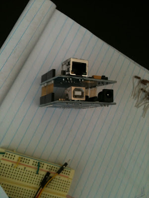
The top picture shows the completed project programmed to display my Twitter feed. The bottom picture shows the Arduino with the Ethernet shield stack on.

In the future I hope to use other inputs from separate boards and have them auto update the twitter account giving the status on whatever I decide to measure. It would be cool to have the reader cycle through multiple RSS feeds too.

This could also be an interesting solution for people not-so-technically inclined. You could build a box for your grandparents that would auto-cycle through their grandchildren's twitter accounts plus their local weather. It would be much cheaper than a computer and hard to mess up - just plug in and the code takes care of the rest!